RODS, CLAMPS and BRACKETS
Hanger Rod
DIMENSION DRAWINGS
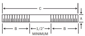
| Rod Dia.A |
Std. Thrd. Lgth. B |
Maximum Recommended Load/lbs. |
Weight per C | ||||||||||||||
|---|---|---|---|---|---|---|---|---|---|---|---|---|---|---|---|---|---|
| C = Length in Inches | |||||||||||||||||
| 650°F | 750°F | 8 | 10 | 12 | 14 | 18 | 24 | 30 | 36 | 42 | 48 | 54 | 60 | 66 | 72 | ||
| 3/8 | 6 | 610 | 540 | *25 | *32 | *38 | 44 | 57 | 76 | 95 | 114 | 133 | 152 | 171 | 190 | 209 | 228 |
| 1/2 | 6 | 1130 | 1010 | *45 | *56 | *67 | 78 | 100 | 134 | 167 | 201 | 235 | 268 | 302 | 335 | 369 | 402 |
| 5/8 | 6 | 1810 | 1610 | *70 | *86 | *104 | 122 | 156 | 208 | 260 | 312 | 364 | 416 | 468 | 520 | 572 | 624 |
| 3/4 | 6 | 2710 | 2420 | *100 | *125 | *150 | 174 | 225 | 300 | 375 | 450 | 525 | 600 | 675 | 750 | 825 | 900 |
| 7/8 | 6 | 3770 | 3360 | *137 | *169 | *204 | 239 | 306 | 408 | 510 | 612 | 714 | 816 | 918 | 1020 | 1122 | 1224 |
| 1 | 6 | 4960 | 4420 | *179 | *214 | *267 | 312 | 400 | 534 | 668 | 801 | 935 | 1068 | 1202 | 1335 | 1469 | 1602 |
| 1 1/8 | 8 | 6230 | 5560 | *226 | *280 | *338 | *395 | 507 | 676 | 845 | 1014 | 1183 | 1352 | 1521 | 1690 | 1859 | 2028 |
| 1 1/4 | 8 | 8000 | 7140 | *279 | *346 | *417 | *488 | 625 | 834 | 1043 | 1251 | 1460 | 1668 | 1877 | 2085 | 2294 | 2502 |
| 1 1/2 | 8 | 11630 | 10370 | *402 | *498 | *600 | *702 | 900 | 1200 | 1500 | 1800 | 2100 | 2400 | 2700 | 3000 | 3300 | 3600 |
| 1 3/4 | 10 | 15700 | 14000 | *548 | *675 | *817 | *947 | *1225 | 1634 | 2042 | 2451 | 2860 | 3268 | 3676 | 4085 | 4493 | 4902 |
| 2 | 10 | 20700 | 18460 | *717 | *882 | *1068 | *1238 | *1602 | 2136 | 2670 | 3204 | 3738 | 4272 | 4806 | 5340 | 5874 | 6408 |
| 2 1/4 | 12 | 27200 | 24260 | *905 | *1120 | *1351 | *1567 | *2026 | *2702 | 3377 | 4053 | 4728 | 5404 | 6080 | 6755 | 7430 | 8105 |
| 2 1/2 | 12 | 33500 | 29880 | *1122 | *1385 | *1699 | *1936 | *2503 | *3338 | 4172 | 5007 | 5841 | 6676 | 7510 | 8345 | 9180 | 10015 |
| * Continuous threaded rod Column headings refer to drawings above. |
|||||||||||||||||
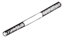
Continuous Threaded Rod
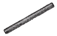
DIMENSION DRAWINGS
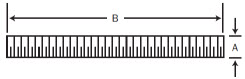
| Rod Size A |
B = Length Ft. |
Max. Recom. Load Lbs. |
Weight per C Ft. |
|||
|---|---|---|---|---|---|---|
| 650°F | 750°F | |||||
| 1/4 | 6 and 12 | 240 | 215 | 12 | ||
| 3/8 | 6 and 12 | 610 | 540 | 30 | ||
| 1/2 | 6 and 12 | 1130 | 1010 | 54 | ||
| 5/8 | 6 and 12 | 1810 | 1610 | 85 | ||
| 3/4 | 6 and 12 | 2710 | 2420 | 124 | ||
| 7/8 | 6 and 12 | 3770 | 3360 | 171 | ||
| 1 | 6 and 12 | 4960 | 4420 | 223 | ||
| Column headings refer to drawings above. | ||||||
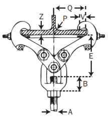
Heavy Duty Beam Clamps

DIMENSION DRAWINGS
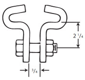
Heavy Duty Beam Clamps Include:
- Two half clamps
- Bolt with nut (assembled)
| Flange Width |
Maximum Flange Thickness |
Weight approx. lbs. ea. |
|---|---|---|
| 4 | 1/2 | 3.82 |
| 5 | 5/8 | 4.35 |
| 6 | 3/4 | 4.52 |
| 7 | 7/8 | 4.84 |
| 8 | 7/8 | 5.10 |
| 9 | 1 | 5.83 |
| 10 | 1 | 6.25 |
| 11 | 1 | 6.67 |
| 12 | 1 | 7.09 |
| Bolt Size |
Stock Size |
Maximum Recom. Load lbs. |
| 5/8 | 1/2 X 2 | 3000 |
| All dimensions are in inches. Column headings refer to drawings above. |
||
Adjustable Beam Clamps
DIMENSION DRAWINGS
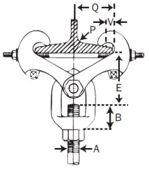
| Clamp Size Number |
Maximum Rod Size A |
Maximum Recommended Load lbs. |
Weight approx. lbs. ea. |
Maximum Beam Flange Thickness |
B | V |
|---|---|---|---|---|---|---|
| 1 | 3/4 | 2710 | 3.9 | 0.60 | 1 1/4 | 1 1/8 |
| 2 | 1 | 4960 | 9.2 | 0.60 | 1 11/16 | 1 1/8 |
| 3* | 1 | 4960 | 13 | 0.60 | 1 11/16 | 1 1/8 |
| 4 | 1 | 4960 | 21.7 | 1.031 | 1 1/2 | 1 1/8 |
| 5* | 1 | 4960 | 33.9 | 1.031 | 1 1/2 | 1 1/8 |
| 6 | 1 1/2 | 11500 | 23.9 | 1.031 | 2 1/8 | 1 1/8 |
| 7* | 1 1/2 | 11500 | 35.8 | 1.031 | 2 1/8 | 1 1/8 |
| 8 | 2 | 11500 | 36.8 | 1.031 | 4 9/16 | 1 1/8 |
| * Furnished with Links **Based on the allowable stresses shown in the ANSI Code for Pressure Piping Column headings refer to drawings above. |
||||||
| Clamp Size Number |
Rod Take-Out E | ||||||||||||
|---|---|---|---|---|---|---|---|---|---|---|---|---|---|
| For Width of Beam Flange | |||||||||||||
| 3 | 4 | 5 | 6 | 7 | 8 | 9 | 10 | 11 | 12 | 13 | 14 | 15 | |
| 1 | 4 1/2 | 4 5/16 | 4 1/16 | 3 5/8 | 2 7/8 | ||||||||
| 2 | 4 3/4 | 4 7/16 | 4 1/8 | 3 3/8 | |||||||||
| 3* | 5 15/16 | 6 | 5 5/16 | 5 | |||||||||
| 4 | 6 13/16 | 6 5/8 | 6 3/8 | 5 7/8 | 5 7/8 | 5 3/8 | 4 13/16 | ||||||
| 5* | 8 1/8 | 7 3/4 | 7 1/8 | 6 5/8 | 6 1/16 | ||||||||
| 6 | 7 3/16 | 7 | 6 3/4 | 6 3/4 | 6 5/16 | 5 13/16 | 5 3/16 | ||||||
| 7* | 8 1/2 | 8 1/8 | 7 1/2 | 7 | 6 7/16 | ||||||||
| 8 | 8 5/8 | 8 7/16 | 8 3/16 | 8 3/16 | 7 3/4 | 7 1/4 | 6 5/8 | ||||||
| * Furnished with Links Column headings refer to drawings above. |
|||||||||||||
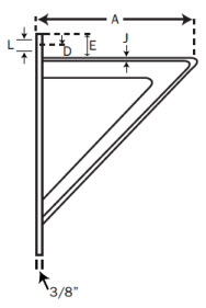
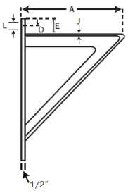
Medium Welded Steel Bracket
DIMENSION DRAWINGS
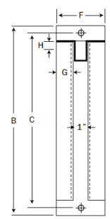
| Bracket Number |
Weight (approx.) lbs. ea. |
A | B | C | D | E | F | G | H | J | L |
|---|---|---|---|---|---|---|---|---|---|---|---|
| 0 | 17.4 | 12 | 18 | 15 1/2 | 1 1/4 | 2 1/2 | 4 | 1 1/2 | 1 1/2 | 1/4 | 13/16 |
| 1 | 27.3 | 18 | 24 | 21 1/2 | 1 1/4 | 2 1/2 | 5 | 1 3/4 | 1 3/4 | 3/16 | 13/16 |
| 2 | 47.7 | 24 | 30 | 27 1/2 | 1 1/4 | 2 1/2 | 5 | 2 | 2 | 1/4 | 13/16 |
| MAXIMUM RECOMMENDED LOAD 3,000 LBS. All dimensions in inches. Column headings refer to drawings above. |
|||||||||||
Heavy Welded Steel Bracket
DIMENSION DRAWINGS
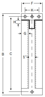
| Bracket Number |
Weight (approx.) lbs. ea. |
A | B | C | D | E | F | G | H | J | L | |
|---|---|---|---|---|---|---|---|---|---|---|---|---|
| 0 | 24.3 | 12 | 18 | 15 1/4 | 1 3/8 | 2 3/4 | 4 | 1 1/2 | 2 | 1/4 | 13/16 | |
| 1 | 51.8 | 18 | 24 | 21 3/8 | 1 7/16 | 2 3/4 | 5 | 2 | 2 | 3/8 | 2 3/4 | 15/16 |
| 2 | 65.8 | 24 | 30 | 27 1/2 | 1 1/2 | 2 3/4 | 5 | 2 | 2 1/2 | 5/16 | 2 1/2 | 1 1/16 |
| 3 | 82.1 | 30 | 36 | 33 1/4 | 1 5/8 | 3 | 5 | 2 | 2 1/2 | 5/16 | 2 1/2 | 1 1/16 |
| 4 | 140.5 | 36 | 42 | 39 | 1 1/2 | 3 | 6 | 2 1/2 | 3 1/2 | 3/8 | 3 1/2 | 1 1/16 |
| 5 | 166.4 | 42 | 50 | 46 | 1 1/2 | 1 1/2 | 6 | 2 1/2 | 3 1/2 | 3/8 | 3 1/2 | 1 1/16 |
| MAXIMUM RECOMMENDED LOAD 3,000 LBS. All dimensions in inches. Column headings refer to drawings above. |
||||||||||||