
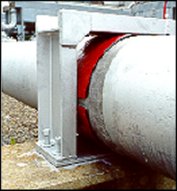


The Ranger II® is an all non-metallic casing isolator/spacer system that uses molded segments to encircle the carrier pipe. Each segment includes at least one molded-in runner and one slide lock. Customer’s may choose from any one of five different size bands to allow correct sizing for carrier pipe O.D. ranges from 0.83″ up to 37.60″ in diameter.
Once sized, the segments are placed around the carrier pipe and cinched together via non-metallic slide locks. Installation is quick and easy while only a small inventory of segments may be used to accommodate a large variety of pipe styles, types and diameters.
* Ranger II® should not be used on concrete carrier pipe. Engineered equal to 304 Stainless Metallic Casing Spacers.
Runners are available in a variety of heights to allow for desired carrier pipe placement in casing.
Separate segments are connected by inserting buckles, with angled locking nubs, into slots on the adjacent segment. A slot accepts Slide-Lock.
| SPECIFICATION | ASTM TEST | VALUE |
|---|---|---|
| Band/Runner Segments |
Injection molded virgin polypropylene | |
| Tensile Strength |
D790 | 3,000 psi (211 kg/cm2) |
| Compressive Strength |
D695 | 3,000 psi (211 kg/cm2) |
| Water Absorbtion |
D570 | 0.1% |
| Temperature | -40°F to 180°F (-40°C to 82°C) | |
| Impact Strength |
D256 | 1.5 ft.lb./in. (0.8 joules/cm) |
| Dielectric Strength |
D149 | 800 V/mil. min. |
| Color | Black |
Liner – none
Runners – Sizes and Configurations
1.5″ (38mmmm) through 6.89″ (175mm)
1 Runner per Segment (Micro, Mini, Midi)
2 Runners per Segment (Medi, Maxi)
Hardware
Non-metallic – Slide Locks – No Metallic Parts
| Skid Height | Distance* |
|---|---|
| 1.5″ (38mm) to 1.97″ (50mm) | 8 ft. |
| 2.56″ (65mm) to 3.54″ (90mm) | 6 ft. |
| 3.94″ (100mm) and greater | 5 ft. |
| * Maximum distance between casing spacers. | |
| Maximum Load (lbs) per Spacer | |||||
|---|---|---|---|---|---|
| Skid Height | MICRO | MINI | MIDI | MEDI | MAXI |
| 1.5″ (38mm) to 1.97″ (50mm) | 175 | 500 | 1,250 | 3,300 | 5,000 |
| 2.56″ (65mm) to 2.95″ (75 mm) | 135 | 400 | 1,000 | 2,600 | 4,000 |
| 3.54″ (90mm) to 3.94″ (100mm) | 120 | 350 | 875 | 2,300 | 3,500 |
| 4.92″ (125mm) to 5.91″ (150mm) | 250 | 625 | 1,650 | 2,500 | |
| 6.89″ (175mm) | 550 | 1,400 | 2,300 | ||
Manufacturer’s warranty statement will be supplied upon request to Allied Corrosion Industries, Inc.
To order Model Ranger II® Non-Metallic Isolators please indicate the following:
| Segment Size |
Carrier Pipe O.D. Range |
Band Width |
Runner Height Options |
Carrier Pipe O.D. Sub-Ranges | Number of Segments |
|---|---|---|---|---|---|
| MICRO | 0.83″ (21mm) to 3.07″ (78mm) |
2.13″ (54mm) |
1.50″ (38mm) 1.97″ (50mm) 2.56″ (65mm) 2.95″ (75mm) 3.54″ (90mm) 3.94″ (100mm) |
0.83″ (21mm) to 1.14″ (29mm) | 3 |
| 1.14″ (29mm) to 1.54″ (39mm) | 4 | ||||
| 1.54″ (39mm) to 1.85″ (47mm) | 5 | ||||
| 1.85″ (47mm) to 2.24″ (57mm) | 6 | ||||
| 2.24″ (57mm) to 2.48″ (63mm) | 7 | ||||
| 2.48″ (63mm) to 3.07″ (78mm) | 8 | ||||
| MINI | 2.48″ (63mm) to 5.51″ (140mm) |
3.15″ (80mm) |
1.50″ (38mm) 1.97″ (50mm) 2.56″ (65mm) 2.95″ (75mm) 3.54″ (90mm) 3.94″ (100mm) 4.92″ (125mm) |
2.48″ (63mm) to 3.07″ (78mm) | 4 |
| 3.07″ (78mm) to 3.86″ (98mm) | 5 | ||||
| 3.86″ (98mm) to 4.49″ (114mm) | 6 | ||||
| 4.49″ (114mm) to 5.51″ (140mm) | 7 | ||||
| MIDI | 5.51″ (140mm) to 16.65″ (423mm) |
5.12″ (130mm) |
1.50″ (38mm) 1.75″ (44mm) 1.97″ (50mm) 2.56″ (65mm) 2.95″ (75mm) 3.54″ (90mm) 3.94″ (100mm) 4.92″ (125mm) 5.91″ (150mm) 6.89″ (175mm) |
5.51″ (140mm) to 6.89″ (175mm) | 4 |
| 6.89″ (175mm) to 8.70″ (221mm) | 5 | ||||
| 8.70″ (221mm) to 10.31″ (262mm) | 6 | ||||
| 10.31″ (262mm) to 12.87″ (327mm) | 7 | ||||
| 12.87″ (327mm) to 14.41″ (366mm) | 8 | ||||
| 14.41″ (366mm) to 16.65″ (423mm) | 10 | ||||
| MEDI | 16.77″ (426mm) to 25.98″ (660mm) |
6.87″ (174mm) |
1.50″ (38mm) 1.97″ (50mm) 2.56″ (65mm) 2.95″ (75mm) 3.54″ (90mm) 3.94″ (100mm) 4.92″ (125mm) 5.91″ (150mm) 6.89″ (175mm) |
16.77″ (426mm) to 21.22″ (539mm) | 4 |
| 21.22″ (539mm) to 25.98″ (660mm) |
5 | ||||
| MAXI | 25.98″ (660mm) to 37.60″ (955mm) |
8.86″ (225mm) |
1.50″ (38mm) 1.97″ (50mm) 2.56″ (65mm) 2.95″ (75mm) 3.54″ (90mm) 3.94″ (100mm) 4.92″ (125mm) 5.91″ (150mm) 6.89″ (175mm) |
25.98″ (660mm) to 30.79″ (782mm) | 6 |
| 30.79″ (782mm) to 37.60″ (955mm) | 7 |
Ranger II® Casing Spacers require more than one segment to complete a spacer. In addition, Ranger II® Casing Spacers are available with a number of different runner height options which are used to guarantee clearance of the mechanical joint, provide for options in carrier pipe positioning in the casing or to compensate for grade elevations adjustments.
Refer to the chart above and the images at the right as you study the following examples.
A 20″ Ductile Iron Pipe (21.60″ O.D. barrel and 28.63′ O.D. bell) inside a 36″ casing with a 0.375″ wall thickness. It is desired that the carrier pipe be centered and restrained in the casing. It is also desired that runners be of equal length.
Step 1:
In the second column of the chart locate the carrier pipe O.D. range which contains 21.60″.
That determines the proper segment size to be MEDI.
Step 2:
In the fifth column of the chart locate the carrier pipe O.D. sub-range which contains 21.60″.
That determines the proper number of segments to be 5.
Step 3: Determine Maximum runner height
The casing I.D. is the O.D. minus twice the wall thickness:
36″ – 2(0.375″) = 35.25″.
The difference between the casing I.D. and the carrier O.D. is
35.25″ – 21.60″ = 13.65″.
Reduce this number by 1″ to 12.65″
(because a minimum 1″ clearance is recommended).
The maximum runner height is half this number:
half of 12.65″ is 6.325″.
In column four and the MEDI row of the chart find the largest available runner height option for the MEDI segment size which is less than the computed maximum.
The available runner height is 5.91″.
Solution: Use 5 MEDI segments with runner heights of 5.91″.
NOTE: This combination will restrain the pipe from flotation in the casing pipe by allowing only about 1.8″ of clearance between the top runners and the casing I.D.
This will center the carrier pipe within approximately 0.9″ of exact center.
A 20″ Ductile Iron Pipe (21.60″ O.D. barrel and 28.63′ O.D. bell) inside a 36″ casing with a 0.375″ wall thickness. It is desired that the runners be choosen to clear the bell on the carrier pipe. It is also desired that runners be of equal length.
Step 1:
Calculate the difference between the barrel O.D. and the bell O.D.
28.63″ – 21.60″ = 7.03″
Step 2:
Add 0.8″ to this difference to provide minimum clearance.
7.03″ + 0.80″ = 7.83″
Step 3:
Divide this number by 2 to obtain the minimum runner height required to clear the bell. 7.83″ divided by 2 is 3.92″
Step 4:
Choose a runner height (from the chart above) between the minimum 3.92″ and the maximum 6.32″.
Solution: Use 5 MEDI segments with runner heights of 3.94″.

Use the following spacing recommendations to determine the number of spacers required for an application.
Spacing Recommendation: Maximum 8 ft.(243.8 cm) between spacers. An isolator/spacer should be placed within 2 ft. (61.0cm) on each side of a coupling or joint or end of the casing.
Upon completion of the installation of the steel pipe encasement, the contractor shall furnish and install a Ranger II® boltless casing spacer on the carrier pipe as described below.
Casing spacers shall be spaced a maximum of eight (8) feet apart along the length of the carrier pipe with one casing spacer within two (2) feet of each side of a pipe joint and the rest evenly spaced. Wood skids are not an acceptable method of supporting the carrier pipe.
1. Casing spacers shall be all non-metallic (polypropylene), molded in segments for field assembly without any special tools. Spacer segments shall be secured around carrier pipe by insertion of a Slide-Lock. The casing spacer polymer shall contain ultraviolet inhibitors and shall have a minimum compressive strength of 3,000 psi, an 800 Volts/mil dielectric strength and impact strength of 1.5 ft-lbs./inch. Each casing spacer shall have full length, integrally molded skids extending beyond the bell or mechanical joint of the carrier pipe.
2. The casing spacers shall be the PSI Ranger II® Casing Spacers as manufactured by Pipeline Seal and Insulator, Inc., Houston, Texas.
3. Spacers shall be at least as wide as listed here:
| Segment Size |
Carrier Pipe O.D. Range |
Band Width |
|---|---|---|
| MICRO | 0.83″ (21mm) to 3.07″ (78mm) |
2.13″ (54mm) |
| MINI | 2.48″ (63mm) to 5.51″ (140mm) |
3.15″ (80mm) |
| MIDI | 5.51″ (140mm) to 16.65″ (423mm) |
5.12″ (130mm) |
| MEDI | 16.77″ (426mm) to 25.98″ (660mm) |
6.87″ (174mm) |
| MAXI | 25.98″ (660mm) to 37.60″ (955mm) |
8.86″ (225mm) |
After insertion of the carrier pipe in the casing, the ends of the casing shall be closed by installing the Link-Seal® end seals and a 1/8″ thick synthetic rubber end seal equal to the PSI Model “C” end seal. Both as manufactured by Pipeline Seal and Insulator, Inc., Houston, TX.
ISO 9001:2000 Registration
Each casing spacer and end seal shall be manufactured at a facility that has a Registered ISO 9001:2000 Quality Management System. Copy of current ISO 9001:2000 Registration shall be provided with material submittal.
Casing Spacer and End Seals