


Model PE Casing Isolators are designed primarily for smaller diameter steel or polyethylene carrier pipes (ANSI O.D. pipe without a bell or mechanical joint). We do not recommend that they be used on any carrier pipe over 24″ in diameter or for installations over 300 feet long without consulting with PSI. PE Isolators should not be used on concrete carrier pipe.
High density (linear), injection molded virgin polyethylene casing isolators/spacers provide positive insulation, high abrasion resistance and low coefficient of friction for a wide variety of double containment carrier/casing pipe applications. They are extremely light in weight and easy to handle during installation.
A ribbed inner surface prevents slippage and guards against carrier pipe coating damage while the outer surface may include any one of several molded runners to accommodate 2″ (50.8mm) x 4″ (101.6mm) or larger carrier/casing differentials.
One piece solid molded segments provide for maximum load bearing. Hardware includes cadmium plated steel studs, nuts and washers. A screwdriver is the only tool needed for installation.

Model PE Casing Isolators are designed primarily for smaller diameter steel or polyethylene carrier pipes (ANSI O.D. pipe without a bell or mechanical joint). We do not recommend that they be used on any carrier pipe over 24″ in diameter or for installations over 300 feet long without consulting with PSI. PE Isolators should not be used on concrete carrier pipe.
Based on 20 ft. (6.0 meters) carrier pipe segments in a casing of not more than 300 ft. (91.5 meters). Consult Allied Corrosion for longer casings and for concrete pipe.
All Model PE Isolator/Spacers should not exceed 5 ft. (1.5 meters) to 8 ft.(2.4 meters) center-to-center. An isolator/spacer should be placed within 2 ft.(0.6 meters) on each side of a coupling or joint and within 1 ft.(0.3 meters) of each end of the casing.
| SPECIFICATION | ASTM TEST | VALUE |
|---|---|---|
| Material | Injection Molded Virgin Polyethylene | |
| Tensile Strength |
D638, D651 | 3,100 – 5,500 psi (218 – 387 kg/cm2) |
| Compressive Strength |
D693 | 3,200 psi (225kg/cm2) |
| Water Absorption |
D570 | 0.1% |
| Temperature | 180°F. Max. (82°C.) | |
| Impact Strength |
D256 | 1.5 – 2.0 ft lb/in. (0.8 – 1.07 newton-meter/cm) |
| Dielectric Strength |
D149 | 450 Volts/Mil. |
| Color | Natural |
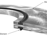
Liner – none
Runners
3/4″ (19mm) through 12″ (305mm) = 2-piece with molded-in runners.
14″ (356mm) and larger = Muliple segments with molded-in runners.
Hardware
Metallic – Bolts and Square Nuts are plated steel.
Non-Metallic – Bolts and Nuts are high temperature plastic.
| Model Size | Band Width | Runner Height |
|---|---|---|
| 3/4 × 2 | 3.0″ (76.19mm) | 5/16 (7.94mm) |
| 1 × 3 | 3.0″ (76.19mm) | 1/2″ (12.7mm) |
| 1 1/4 × 3 | 3.0″ (76.19mm) | 1/2″ (12.7mm) |
| 1 1/2 × 3 | 3.0″ (76.19mm) | 1/2″ (12.7mm) |
| 2 × 4 | 4.0″ (101.6mm) | 5/8″ (15.88mm) |
| 2 1/2 × 5 | 4.0″ (101.6mm) | 5/8″ (15.88mm) |
| 3 × 6 | 4.0″ (101.6mm) | 5/8″ (15.88mm) |
| 4 × 6 | 4.0″ (101.6mm) | 9/16″ (14.29mm) |
| 4 × 8 | 4.0″ (101.6mm) | 1″ (25.4mm) |
| 6 × 8 | 4.0″ (101.6mm) | 9/16″ (14.29mm) |
| 6 × 10 | 4.0″ (101.6mm) | 1″ (25.4mm) |
| 6 × 10S* | 4.0″ (101.6mm) | 9/16″ (14.29mm) |
| 8 × 10 | 4.0″ (101.6mm) | 9/16″ (14.29mm) |
| 8 × 12 | 5.0″ (127.0mm) | 1″(25.4mm) |
| 8 × 12S* | 5.0″ (127.0mm) | 7/8″ (22.23mm) |
| 10 × 14 | 5.0″ (127.0mm) | 7/8″ (22.23mm) |
| 10 × 16 | 5.0″ (127.0mm) | 7/8″ (22.23mm) |
| 12 × 16 | 5.0″ (127.0mm) | 7/8″ (22.23mm) |
| All Multiple Segments* (4″ Differentials) |
6.25″ (158.75mm) | 1″ (25.4mm) |
| All Multiple Segments* (6″ Differentials) |
6.25″ (158.75mm) | 1 1/2″ (38.1mm) |
| * S indicates Somastic Coated Pipe Model PE sized for nominal steel and IPS pipe. |
||

| Size (Nominal ANSI) |
Specification Data |
Approximate Shipping Data |
||||
|---|---|---|---|---|---|---|
| Carrier | Minimum Casing |
Effective Skid Height |
Number Of Segments Per Unit |
Number Of Units Per Case |
Per Unit Weights In Pounds |
Per Case Cu. Ft. |
| 3/4″ | 2″ | 5/16″ | 2 | 10 | .05 | .09 |
| 1″ | 3″ | 1/2″ | 2 | 10 | .15 | .13 |
| 1-1/4″ | 3″ | 1/2″ | 2 | 10 | .20 | .14 |
| 1-1/2″ | 3″ | 1/2″ | 2 | 10 | .20 | .18 |
| 2″ | 4″ | 5/8″ | 2 | 10 | .50 | .34 |
| 2-1/2″ | 5″ | 5/8″ | 2 | 10 | .57 | .51 |
| 3″ | 6″ | 5/8″ | 2 | 10 | .65 | .47 |
| 4″ | 6″ | 9/16″ | 2 | 10 | .77 | .34 |
| 4″ | 8″ | 1″ | 2 | 10 | 1.00 | .47 |
| 6″ | 8″ | 9/16″ | 2 | 10 | 1.10 | .74 |
| 6″ | 10″ | 1″ | 2 | 10 | 1.65 | .91 |
| 6″(S) | 10″ | 9/16″ | 2 | 10 | 1.92 | .91 |
| 8″ | 10″ | 9/16″ | 2 | 10 | 1.45 | .56 |
| 8″ | 12″ | 1″ | 2 | 10 | 2.20 | 1.13 |
| 8″ (S) | 12″ | 7/8″ | 2 | 10 | 2.29 | 1.13 |
| 10″ | 14″ | 7/8″ | 2 | 10 | 2.37 | 1.35 |
| 10″ (S) | 16″ | 7/8″ | 2 | 10 | 2.55 | 1.35 |
| 12″ | 16″ | 7/8″ | 2 | 10 | 2.72 | 1.67 |
| (S) means Somastic coated pipe | ||||||
| Size (Nominal ANSI) |
Specification Data |
Approximate Shipping Data |
|||||
|---|---|---|---|---|---|---|---|
| Carrier | Minimum Casing |
Effective Skid Height |
Number Of Segments Per Unit |
Number Of Units Per Case |
Per Unit Weights In Pounds |
Per Case Cu. Ft. |
|
| Full LS4 | Half LS2 | ||||||
| 12″(S) | 18″ | 1″ | 3 | 1 | 10 | 4.50 | 2.64 |
| 14″ | 18″ | 1″ | 3 | 1 | 10 | 4.50 | 2.64 |
| 16″ | 20″ | 1 | 4 | 10 | 5.00 | 2.98 | |
| 18″ | 22″ | 1″ | 4 | 1 | 10 | 5.75 | 3.31 |
| 20″ | 24″ | 1″ | 5 | 10 | 6.25 | 3.65 | |
| 22″ | 26″ | 1″ | 5 | 1 | 10 | 7.00 | 3.95 |
| 24″ | 28″ | 1″ | 6 | 10 | 7.50 | 4.33 | |
| 26″ | 30″ | 1″ | 6 | 1 | 10 | 8.25 | 4.67 |
| 28″ | 32″ | 1″ | 7 | 10 | 8.75 | 5.01 | |
| 30″ | 34″ | 1″ | 7 | 1 | 10 | 9.50 | 5.34 |
| 32″ | 36″ | 1″ | 8 | 10 | 10.00 | 5.63 | |
| 34″ | 38″ | 1″ | 8 | 1 | 10 | 10.75 | 5.97 |
| 36″ | 40″ | 1″ | 9 | 10 | 11.25 | 6.30 | |
| 38″ | 42″ | 1″ | 9 | 1 | 10 | 12.00 | 6.64 |
| 40″ | 44″ | 1″ | 10 | 10 | 12.50 | 6.98 | |
| 42″ | 46″ | 1″ | 10 | 1 | 10 | 13.25 | 7.32 |
| 44″ | 48″ | 1″ | 11 | 10 | 13.75 | 7.66 | |
| 46″ | 50″ | 1″ | 11 | 1 | 10 | 14.50 | 7.99 |
| 48″ | 52″ | 1″ | 12 | 10 | 15.00 | 8.33 | |
| (S) means Somastic coated pipe. | |||||||
| Size (Nominal ANSI) |
Specification Data |
Approximate Shipping Data |
|||||
|---|---|---|---|---|---|---|---|
| Carrier> | Minimum Casing |
Effective Skid Height |
Number Of Segments Per Unit |
Number Of Units Per Case |
Per Unit Weights In Pounds |
Per Case Cu. Ft. |
|
| Full HS6 | Half HS6A | ||||||
| 14″ | 20″ | 1.5″ | 3 | 1 | 10 | 4.50 | 2.64 |
| 16″ | 22″ | 1.5″ | 4 | 10 | 5.00 | 2.98 | |
| 18″ | 24″ | 1.5 | 4 | 1 | 10 | 5.75 | 3.31 |
| 20″ | 26″ | 1.5″ | 5 | 10 | 6.25 | 3.65 | |
| 22″ | 28″ | 1.5″ | 5 | 1 | 10 | 7.00 | 3.95 |
| 24″ | 30″ | 1.5″ | 6 | 10 | 7.50 | 4.33 | |
| 26″ | 32″ | 1.5″ | 6 | 1 | 10 | 8.25 | 4.67 |
| 28″ | 34″ | 1.5″ | 7 | 10 | 8.75 | 5.01 | |
| 30″ | 36″ | 1.5″ | 7 | 1 | 10 | 9.50 | 5.34 |
| 32″ | 38″ | 1.5″ | 8 | 10 | 10.00 | 5.63 | |
| 34″ | 40″ | 1.5″ | 8 | 1 | 10 | 10.75 | 5.97 |
| 36″ | 42″ | 1.5″ | 9 | 10 | 11.25 | 6.30 | |
| 38″ | 44″ | 1.5″ | 9 | 1 | 10 | 12.00 | 6.64 |
| 40″ | 46″ | 1.5″ | 10 | 10 | 12.50 | 6.98 | |
| 42″ | 48″ | 1.5″ | 10 | 1 | 10 | 13.25 | 7.32 |
| 44″ | 50″ | 1.5″ | 11 | 10 | 13.75 | 7.66 | |
| 46″ | 52″ | 1.5″ | 11 | 1 | 10 | 14.50 | 7.99 |
| 48″ | 54″ | 1.5″ | 12 | 10 | 15.00 | 8.33 | |
| (S) means Somastic coated pipe | |||||||
Casing isolators/spacers shall be PSI Model PE molded from high density polyethylene plastic in two segments for applications on carrier pipe diameters of 12″ and under. Model PE isolator/spacers will be provided in multiple segments for applications on carrier pipe diameters of over 12″. Each spacer segment shall be a solid, non-welded molded piece designed for accommodating a specific size carrier pipe O.D.
Each casing spacer shall be manufactured at a facility that has a Registered ISO 9001:2000 Quality Management System. A copy of the current ISO 9001:2000 registration shall be provided with material submittal.
Approved manufacturer: Pipeline Seal and Insulator, Inc.
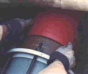
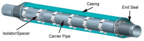
After insertion of the carrier pipe in the casing, the ends of the casing shall be closed by installing a PSI Model “C”, Model “S” or Model “FW” casing end seal as manufactured by Pipeline Seal and Insulator, Inc., Houston, TX.
(Carrier Pipe Must Centered Within Casing)
After insertion of the carrier pipe in the casing, the ends of the casing shall be closed by installing the Link-Seal® end seals and a 1/8″ thick synthetic rubber end seal equal to the PSI Model “C” end seal. Both as manufactured by Pipeline Seal and Insulator, Inc., Houston, TX.
The foregoing performance data is intended as guideline material only and is based on assumptions of general and reasonable use. Performance suitability for any specific application should be determined by the user.
Casing Spacer and End Seals Engineering Manual and Buyers Guide