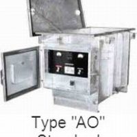
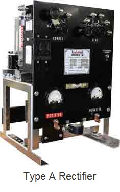
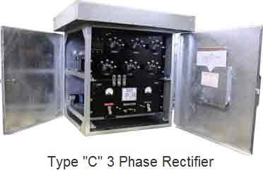
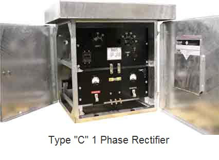
Universal Rectifier Air Cooled Standard Line
Heavy duty, pole mountable, air cooled cathodic protection rectifiers.
Quick Facts:
- Pole mountable rectifiers
- Weatherproof to NEMA 3R
- Stainless Steel Construction
- Alternate output control
Applications:
- Pipelines
- Tank Farms
- Storage Fields
- Non Hazardous Locations
Universal Rectifier Standard Line Advantages
The “Standard Line” air cooled, cathodic protection rectifiers are recognized as industry leading in quality, workmanship and service life. Many years of field-proven service prove their superior design. Conservative equipment ratings, controlled manufacturing techniques, plus many extra features ensure long and trouble-free operation.
Universal Rectifier Standard Line Applications
Typical cathodic protection applications for the air cooled rectifier line include pipelines, tank farms, storage fields, and other non-hazardous locations where continuous duty, DC power is required.
Universal Rectifier Standard Line Features
- Weatherproof to NEMA 3R
- Heavy duty 11-gauge hot dip galvanized cabinet with Stainless Steel Hardware
- Stainless Steel, perforated screens
- Front and side opening doors for easy maintenance
- Heavy duty, draw-pull, stainless steel cabinet latch
- Slide-out equipment racks, separate Transformer and Stack assemblies for units over 1200 watts
- Heavy duty transformer with 15% over-design for reserve capacity
- Minimum 18-step voltage control link bar taps
- Quick-change, heavy-duty knobs for changing tap link bars
- Minimum 5/16″ diameter, soldered tap changing studs
- 3/16″ Grade XX, Phenolic front panel
- Accessible front panel Total precision shunt
- Magnetic AC Input circuit breaker
- Magnetic AC Secondary Breakers on all units less than 100 amps (instead of fuses)
- Hoyt, separate analog, 2-1/2″ round, volt and amp meters
- Silicon diodes protected by surge suppressors and current limiting breakers < 100 Amps or fuses
- All electrical connection hardware is Nickel Plated and double-nutted or soldered
- Multi-strand, high temperature, insulated flexible wiring
- Terminal block for AC input wires
- Primary tap change panel for dual input voltages (Single Phase models only)
- Safety shield panel supplied on all units over 65 Volts DC
Universal Rectifier Air Cooled Standard Line Optional Features
Optional Features
- Variety of AC voltage inputs, Single Phase, Three Phase, 50 or 60 Hertz
- AC and/or DC High Energy lightning protection
- Efficiency filter chokes
- Communication filters
- Meter switches
- Pedestal, base mounting legs, Wall Mount
- Power-on indicator light
- DC failure warning lights
- DC circuit breakers < 100 amps or fuses
- 115 VAC convenience outlet
- Powder-coated cabinet finishes (White or Gray standard
- Optional cabinet materials, such as aluminum or stainless steel
- Anodized finish for aluminum cabinets
- Anodized finish with clear coat for aluminum cabinets
- Additional voltage control link bar taps
- Alternate output control (constant current, constant voltage, constant potential and constant potential with IR drop free feature)
- NRTL / ETL third-party certification
- Other options per customer request
Universal Rectifier Air Cooled Standard Line Wattage & Weight
| Single Phase | Three Phase | ||||
|---|---|---|---|---|---|
| Maximum DC Watts |
Shipping Weight lbs. |
Maximum DC Watts |
Shipping Weight lbs. |
||
| C a s eS i z e |
A | 1200 | 135 | ||
| B | 2800 | 185 | 1000 | 225 | |
| C | 6000 | 300 | 6500 | 385 | |
| D | 10,000 | 400 | 12,000 | 625 | |
| E | 12,000 | 525 | 18,000 | 750 | |
| Each rectifier is custom built and will vary in weight: The weights above are approximate. |
|||||
Universal Rectifier Air Cooled Standard Line Typical Dimensions
| Letters Reference the Drawing | |||||||||||||
|---|---|---|---|---|---|---|---|---|---|---|---|---|---|
| A | B | C | D | E | F | G | H | I | J | K | L | ||
| C a s eS i z e |
A | 14.5 | 12 | 19.5 | 3 | 14.5 | 19 | 26.25 | 3 | 7.5 | 6 | 7.5 | 3 |
| B | 17.5 | 15.5 | 23.5 | 3.5 | 18 | 23 | 32 | 3 | 9 | 8 | 10 | 6 | |
| C | 22.5 | 21.5 | 23.5 | 3.5 | 24 | 28 | 32 | 3 | 9 | 10 | 15 | 10 | |
| D | 28.5 | 22.5 | 23.5 | 3.5 | 25 | 34 | 32 | 3 | 9 | 12 | 21 | 10 | |
| E | 34 | 28 | 33 | 5 | 33 | 44 | 41.25 | 3 | 18.5 | 14 | 25 | 14 | |
| Case Dimensions are in inches. | |||||||||||||
Universal Rectifier Air Cooled Standard Line Ordering Code/ Model Number
- Position #1: MODEL
- A = Air Cooled Line, Air Cooled
- Position #2: TYPE
- S = Standard Rectifier (Manual Taps)
- C = Constant Current (Reactor Style)
- D = Constant Current (Solid State)
- E = Constant Voltage (Solid State)
- P = Constant Potential (Solid State)
- I = Constant Potential IR Free (Solid State)
- M = Multiple Modes (Specify Modes Required)
- V = Variac Control
- Position #3: COOLING
- A = Air Cooled
- Position #4: STACK TYPE
- I = Silicon (Recommended)
- E = Selenium
- Position #5: DC VOLTS
- List Maximum DC Voltage Desired
- Position #6: DC AMPS
- List Maximum DC Amperage Desired
- Position #7: AC INPUT
- AA = 115/230, 1 phase set for 115 vac
- AB = 115/230, 1 phase set for 230 vac
- BA = 230/460, 1 phase set for 230 vac
- BB = 230/460, 1 phase set for 460 vac
- CA = 230/460, 3 phase set for 230 vac
- CB = 230/460, 3 phase set for 460 vac
- EA = 115/460, 1 phase set for 115 vac
- EB = 115/460, 1 phase set for 460
- G = 115, 1 phase only
- H = 230, 1 phase only
- D = 208, 3 phase
- F = Specify
- Position #8: SPECIAL FEATURES
- C = AC and DC arrestors
- D = DC arrestor
- E = AC arrestor
- F = Filter Choke
- G = Communications Filter
- H = Meter Switches
- I = Base Mounting
- J = Power On Indicator Light
- K = DC Failure Light
- M = DC Breaker (> 100 amps) or Fuse
- R = 115 VAC Convenience Outlet
- N = Powder Coated Cabinet (hot-dip galvanized standard on most models)
- O = Aluminum Cabinet
- T = Anodized Aluminum
- U = Anodized Aluminum with Clear Coat
- P = Additional Voltage Control Link Bar Taps
- S = Multiple Rectifiers in One Case (qty.)
- Q = Other, Specify


Related products
-
- Reference Electrodes and Test Stations, Testing Equipment, Tinker and Rasor
At Grade Test Stations
- $1.00
- Add To Quote This product has multiple variants. The options may be chosen on the product page