Modular Impressed Current Linear Anodes, Designed to be Suitable and Easily Installed in Any Size System
The EDI Model AT Anode allows for very flexible designs, with no splicing or weldments required during installation
Features
Design Flexibility - Modular design permits multitude of anode configurations
Rapid Installation - No field splices or weldments
Light weight - Very easy to ship and handle
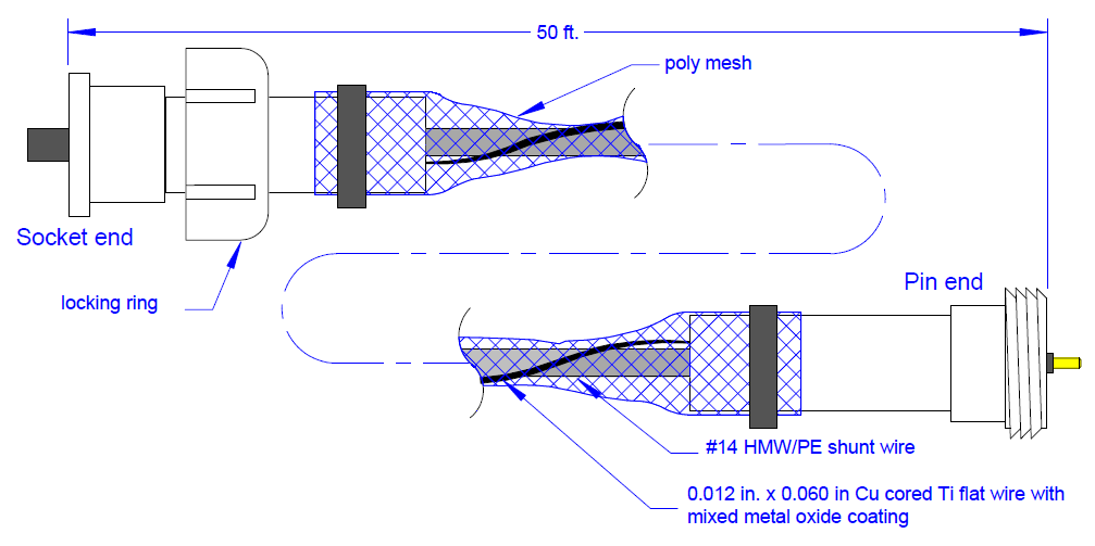
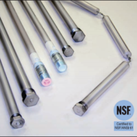
The Model AT Linear Modular Anode System is an impressed current linear anode system which permits maximum design flexibility. It consists of a copper cored titanium flat wire coated with mixed metal oxide and attached to a #14 AWG HMW/PE insulated bus wire. The wire pair is surrounded by a flexible plastic mesh. Individual anodes are 50 ft. long and are easily connected in the field to form a hermetically sealed joint. This allows the design engineer to choose a layout which is best suited for the application.
Perhaps the most significant feature of the Model AT is its unique connector system. Each anode is supplied with a pin connector on one end and a socket connector on the opposite end which can be mated either to another anode section to form a string or to a power feed cable. Specially developed “tee” connectors allow intermediate current feeds on long strings. These connectors are designed for underwater cable connections and are being used successfully on other EDI products in turbulent aqueous solutions. All connections are factory made and sealed which means that there are no splices or weldments required in the field. Installation can be completed in substantially less time than any other system. For example, it takes less than 6 man-hr. to install this anode system in a 60 ft diameter tank.
EDI's Modular Linear Anodes are 50 feet long, and are easily connected together to fit any system. Suitable for underwater use.
Typical Applications
Above Ground Storage Tank Bottoms
Pipelines
Marine Structures
Diagram of Modular Linear Anodes
Modular Linear Anodes have a socket end and a pin end, which easily mate together and are secured with a locking ring. No splices or weldments required in the field.
Pin and socket are brass alloy 360
Connector body is Neoprene
Power rating = 15 amps
Insulation rating = 750 V
Minimum insulation thickness = 0.040"
Contact resistance< 0.01 ohm
Insulation resistance > 200 megaohm after wet mating
Pressure rating = 20 kpsi
Rated for 500 wet matings
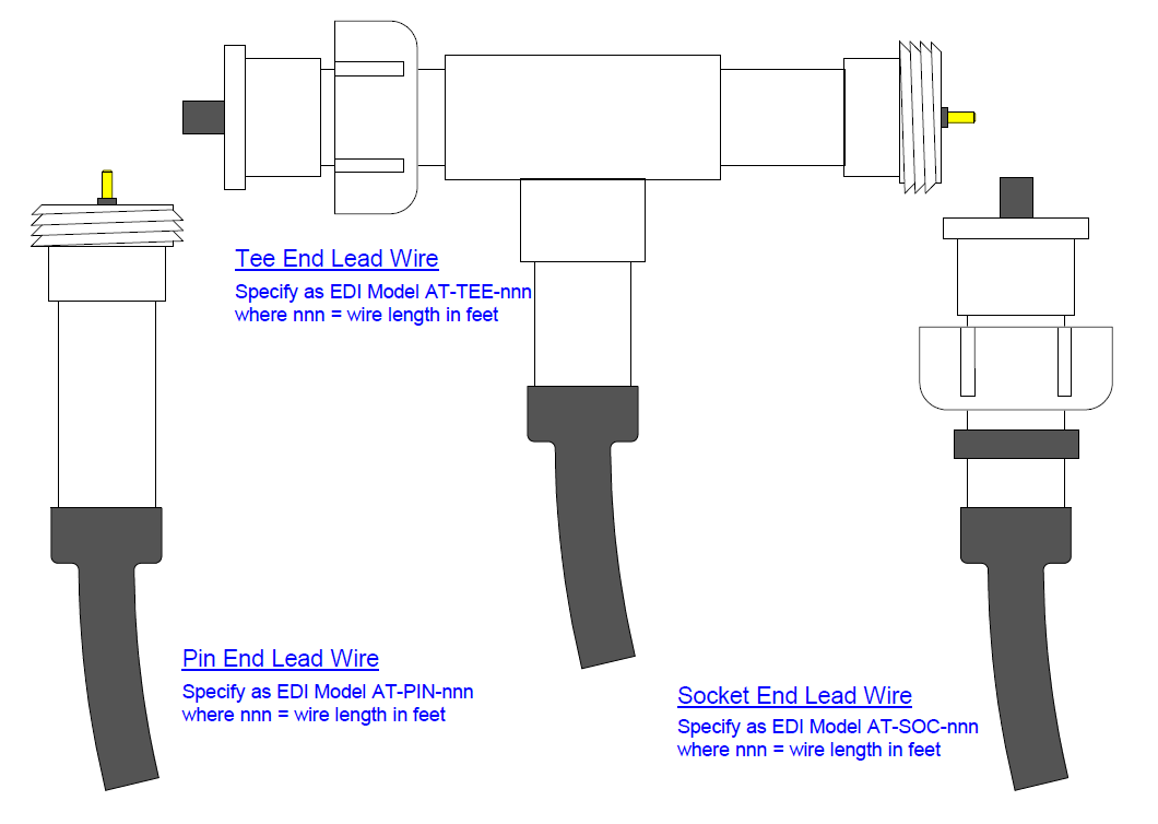
Diagram of Anode Power Feeds
Modular Linear Anode Installation
AT Anode Power Feeds
Modular design of anodes allow for flexible and quick installation.
AT Anode Branch and End Plugs
The Tee Branch and Connection plugs of the AT Anode System make virtually any configuration possible
Notes:
1.) When connector halves are fully mated, points “A” will align.
2.) Current output not to exceed 10 mA/ft/wire. Use multiple wire anodes for higher current output.
3.) Individual anodes may be interconnected to form strings of any desired length. Power feeds must be no more than 1,000 feet apart on single wire anodes.
4.) Current should be fed into anode strings from both ends. Longer strings should have additional intermediate feeds.
5.) Assemble individual anodes into strings by pressing pin end fully into socket end. The joint and be made permanent by using any solvent cement suitable for use with CPVC.
Anode Layout
The anode should be placed as deep as possible, preferably, directly on the polymer liner. Shallower placements will reduce the spread of CP current. Begin the layout at the ring wall next to the access port and work toward the center of the tank. When using a stepped spiral array, the first loop will be a complete circle located at half the anode spacing distance, s, away from the ring wall. At the end of this loop, the anode steps over to start the second loop located a distance s from the first loop. The radius of the bend between the loop and the step shall be no smaller than 6 inches (15 cm) to avoid damaging the anode. The step does not have to be perpendicular to the anode; an offset of 30° to 45° is optimum. When using other array designs, layout details should be as specified by the CP system designer. Embedded reference electrodes should be placed mid-way between anode strings. Other sensors, such as 4-wire resistivity probes or ER probes, should be located close to the reference electrodes.
Anode power leads are connected to both ends of the anode strings. Tee-end lead wires are used to provide intermediate power feeds. Distance between power feeds must not exceed 1000 feet (300 m). Remove the protective vinyl caps when ready to connect individual anode sections or power feeds. Press the ends firmly together to ensure the connector is fully
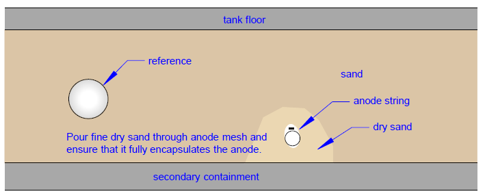
seated; the PVC housing flanges should be about 1 – 2 mm apart. Tighten the securing nut hand tight. Anodes can be held in position by either directly taping the joints to the polymer liner or using small sandbags. Cover the anode by pouring fine dry sand directly on the mesh and ensuring that it penetrates to encapsulate the anode. The sand should be finer than 0.6 mm (#30 sieve) and cover the mesh by about ½ inch (1.5 cm). When doing end-to end continuity checks, each anode has a resistance of about ¼ Ω; lead wire resistance is about ½ Ω per 100 ft. (30 m).
Stepped Spiral Array
Begin anode layout at the ringwall and work toward the center.
Lead wires are connected to both ends of the anode string. Tee End lead wires are used for intermediate power feeds. Distance between power feeds must not exceed 1,000 feet (300 m).
Linear Anode Array Layout Concepts
The EDI AT Anode System allows arrays of virtually any configuration to be assembled in the field using just a few modular components.
Backfilling and Installing Tank Floor
The anode array is covered with sand to the depth specified by the CP system designer. If the sand is too dry, this can cause problems during commissioning because the resistivity will be too high to permit passage of adequate current to polarize the tank bottom. Adding moisture to the sand after it has been graded but before the floor has been installed will make it possible to properly commission the system.
All cathodic protection systems can be easily damaged at this stage of construction. If mechanized equipment is used, extreme care must be taken to ensure that the system is not damaged. Wires can be severed, reference electrodes can be crushed, and sections of the anode can be dragged out of their intended position. The CP installer should continuously monitor electrical continuity on the anode circuits during sand installation so that any damage can be located and quickly corrected.
Commissioning
Before commissioning the system, there must be sufficient product in the tank to ensure that the bottom is in complete contact with the sand. If the sand bed is damp enough to conduct current, the system can be commissioned by setting the rectifier to produce the desired shift in the tank floor potential. Once that has been attained, no further adjustment should be made to the rectifier output voltage. Note: rectifier voltage should not exceed 25V. As the system operates, the sand will dry out making the environment less corrosive. When this happens, current output will be reduced. When the sand re-wets due to rain or flooding, the current will return to the level necessary to provide protection.
We care about your privacy! In order to run a successful website, we are setting cookies and accessing and storing information on your device for various purposes. By continuing to browse this site, you are agreeing to our use of cookies.
If you wish to disable cookies, please visit our Privacy Policy for more information.