
PSI Casing Spacers Standard Model Guidelines
Terminology
Casing Spacer and Casing Isolator are the same product and serve the same application needs. The casing isolator terminology originated in the Energy Market in the 1960’s. PSI prefers the term Casing Spacer.
The industry also uses the following terms in lieu of Casing Spacer:
|
|
Carrier Pipe Diameter Range
Carrier Pipe Insertion Length
| Non-metallic Casing Spacers | Metallic Casing Spacers | |||||
|---|---|---|---|---|---|---|
| Model PE |
Model HT |
Model AZ |
Ranger II® | Models C & S 8″ band |
Models C & S 12″ band |
|
| Steel | E | E | S | E | E | E |
| Steel (Mortar Coated) | U | U | U | U | NR | E |
| Ductile Iron | U | U | U | G | G | E |
| Cement | U | U | U | U | E | E |
| Profile Pipe | U | U | U | S | E | E |
| Clay | NR | NR | U | U | E | E |
| HDPE | NR | NR | S | E | E | E |
| PVC Water Pipe | NR | NR | G | E | E | E |
| PVC Sewer Pipe | NR | NR | G | E | E | E |
| Legend: E = Excellent NR = Not Recommended G = Good F = Fair S = Satisfactory U = Unsatisfactory |
||||||
| Non-metallic Casing Spacers | Metallic Casing Spacers | ||||||
|---|---|---|---|---|---|---|---|
| Model PE |
Model HT |
Model AZ |
Ranger II® | Models C8 – C12 |
Models S8 – S12 |
Models SL8 |
|
| Band Material | Polyethylene | Polycarbonate | Polypropylene | Polypropylene | 14 Guage PVC Coated Steel |
14 Guage 304 Stainless Steel |
16 Guage 304 Stainless Steel |
| Runner Material | Polyethylene | Polycarbonate | Polypropylene | Polypropylene | Glass Reinforced Nylon |
Glass Reinforced Nylon |
Glass Reinforced Nylon |
| Riser Material | None | None | None | None | 10 Guage Coated Steel |
10 Guage Stainless Steel |
12 Guage Stainless Steel |
| Liner Material | None | High Temp Plastic |
None | None | Polyvinyl Chloride |
Polyvinyl Chloride |
Polyvinyl Chloride |
| Hardware | Plated Steel |
Plated Steel |
Plated Steel |
None | Plated or 304 Stainlesss Steel |
304 Stainless Steel |
304 Stainless Steel |
| Compressive Strength | 3,200 psi | 12,500 psi | 3,000 psi | 3,000 psi | 18,000 psi | 18,000 psi | 18,000 psi |
| Temperature Range | 180° Max | 280° Max | -40° to 180° | -22° to 212° | -40° to 170° | -40° to 170° | -40° to 170° |
PSI Casing Spacers Runner Height Options
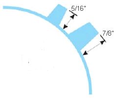
Model PE Non-metallic Casing Spacer
|
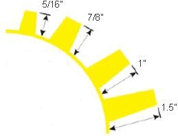 For 3/4″ to 12″ diameters: runner heights range from 5/16″ to 7/8″. For 14″ to 48″ diameters: runner heights range from 1″ to 1 1/2″. |
Model Ranger II® Non-metallic Casing Spacer
|
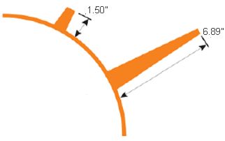 For 0.83″ to 37.60″ diameters: runner heights range from 1.50″ to 6.89″. |
Model AZ Non-metallic Casing Spacer
|
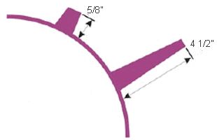 For 3.85″ to 13.75″ diameters: runner heights range from 5/8″ to 4 1/2″. |
Model HT (High Temp) Non-metallic Casing Spacer
|
 For 3/4″ to 12″ diameters: runner heights range from 5/16″ to 7/8″. |
| Model C Coated Metallic Casing Spacer Model S Stainless Steel Metallic Casing Spacer
|
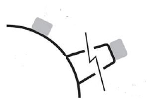 For 4.00″ to 120.0″ diameters: runner heights are customized to the application. Runner may be attached directly to band. Runner height is positioned to specification by 10 or 7 guage risers. |
| If casing pipe has offsets or weld beads in excess of 1/8″, consider using a metallic casing spacer. | |
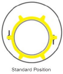
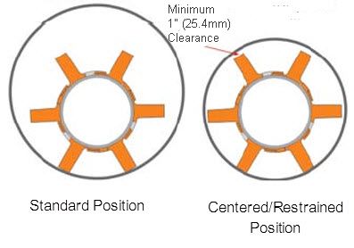
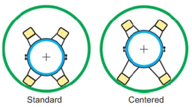
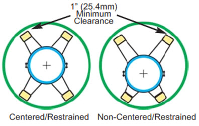
PSI Casing Spacers Positioning Guidelines
Model PE Non-metallic Casing Spacer
|
 |
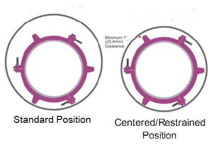
Model Ranger II® Non-metallic Casing Spacer
|
 |
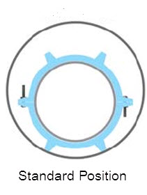
Model AZ Non-metallic Casing Spacer
|
 |
Model HT (High Temp) Non-metallic Casing Spacer
|
 |
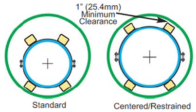
| Model C Coated Metallic Casing Spacer Model S Stainless Steel Metallic Casing Spacer
|
   |

