Installation of PSI Isolating Gaskets


Installation
- Open insulating kit to inspect and determine that the components are as specified. It should be no greater than the flange I.D. unless so ordered. Contractor or installation crew must handle the gasket with due care to prevent flexural stress in the gasket during unpacking and installation.
- Flanges shall be free of pits, gouges, rust, debris, oil and grease. Surface finish shall be no greater than 250 RMS. Refinish flange faces if corrective measures do not meet the foregoing. Check flange and bolt hole spot facings for burrs, etc. and clear from facings.
- Check bolts and nuts and clean. Apply non-conductive lubricant to all threads and flange side of nuts. If bolts are used rather than studs, inspection of the unthreaded shank area should take place to insure isolation sleeves will fit. PSI sleeve material is designed to fit over standard size threaded studs.
- Align flanges so they are concentric and parallel and install gasket carefully. USE NO LUBRICANT, GREASE OR ADHESIVES ON EITHER THE GASKET OR FLANGE FACES. Guard against damaging sealing element.
- Line up bolt holes with non-tapered drift pins using three at 120° degrees separation (particularly large flanges),or at least two at 180° degrees separation.
- Insert bolt sleeves. Do not force. If force is needed, recheck alignment and for sleeve damage. Follow up with studs, nuts, and washers, placing lubricated face of nut next to steel washer (this will help to reduce galling of the insulating washer on flange, should the whole bolt assembly rotate). Galling: If serious galling of insulating washers persists, replace with high strength washers. (minimum 50K psi).
- Some companies specify 1/4″ larger bolt holes than bolt diameters, one flange only, to allow for easier line-up in the field. In worst cases, the insulating washer can be as much as 1/4″ off-center of the oversize bolt hole, resulting in a substantially reduced flange bearing area for the insulating washer.With flange assemblies of this type, the insulating washer should each be sandwiched between two steel, back-up washers for additional support.
- When insulating both sides of a flanged assembly, insulating bolt sleeves must be sized to compensate for additional washers.
- Initially cross-tighten bolts until flange to gasket contact has been made.
- Check for a flange segment that may show a gap or separation between gasket and flanges, using flashlight, calipers, or feeler gauge. If one exists, the flanges are not parallel.
- Directly 180° degrees opposite widest part of indicated gap, loosen nuts, even if only finger tight, one or more turns. Return to segment with gap and tighten until both flanges are in contact with gasket retainer. This procedure is necessary to prevent restriction of flange rotation over the fulcrum formed by the outer edge of the two raised faces at points in contact with gasket retainer. The restriction will cause exceptionally high flange to gasket clamp loading at this point, with possible damage to gasket retainer, plus diverting necessary clamp loading bolt torque energy to correcting alignment on the opposite segment.
- Re-tighten loosened nuts and proceed with torquing of the bolts according to PSI diagram, to 10-15% of specified torque. Remove drift pins and replace with bolts, nuts and washers, tightened to the same values as others in place.
- Repeat torque sequence, increasing to 50% of balance.
- Repeat tightening to final torque.
- Optional – it is always a good policy to go completely around flange checking bolt to bolt for proper torque, particularly on large diameter piping systems.
- All the above should be done with torque wrenches (mechanical and hydraulic) or with a stud tension measuring device.
- PSI suggests sealing gaskets are not to be reinstalled or reused.
Always wear appropriate safety equipment!
Important: Check gasket for flange type on which to be used (ie). Slip or weld-neck etc. if in doubt do not install, consult Allied Corrosion Industries, Inc.
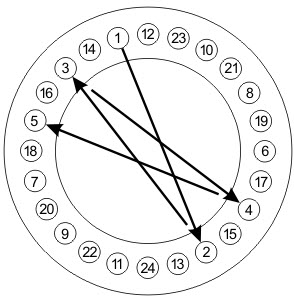
To provide even sealing pressure on a flange gasket it is recommended that the bolts be “snugged” up in the sequence shown on chart until the flange faces are in contact with the gasket. After the flange faces are in contact with the gasket firmly tighten the bolts in the same sequence. Note: Although this diagram shows 24 bolts, the same basic procedure should be used with flanges having more or less bolts. When installing gaskets made of compressible dielectric material and tightened cold; “hot flow” of the gasket material may occur under operating conditions, resulting in loss of bolt pressure. It is advisable therefore, to re-tighten bolts after operating temperature has been reached — preferably at zero line pressure and ambient temperature. Under no circumstances should the system be allowed to return to operating temperature after the initial cycling to ambient temperature without checking and re-tightening bolts where needed.

Suggested Torque Values — Theoretical
Pipeline Seal & Insulator, Inc. does not take responsibility for any of these torque values, they are theoretical values. These bolt torque values are intended for use as guidelines only and are based on ideal conditions, perfect flanges, flange alignment & new well lubricated bolts/nuts according to the national boiler code, Installed in accordance with the PSI Flange Makeup Procedure. Torque values are based on using weld-neck flanges and lubricated stud bolts with a 0.2 friction factor.
Actual torque values to be determined by user!
Always wear safety equipment,
| Size inches |
Number of Bolts |
Bolt Diameter |
Suggested Torque Ft. Lbs. |
|---|---|---|---|
| 1 | 4 | 0.5 | 40 |
| 1 1/4 | 4 | 0.5 | 40 |
| 1 1/2 | 4 | 0.5 | 40 |
| 2 | 4 | 0.625 | 80 |
| 2 1/2 | 4 | 0.625 | 80 |
| 3 | 4 | 0.625 | 110 |
| 3 1/2 | 8 | 0.625 | 80 |
| 4 | 8 | 0.625 | 100 |
| 5 | 8 | 0.75 | 120 |
| 6 | 8 | 0.75 | 130 |
| 8 | 8 | 0.75 | 130 |
| 10 | 12 | 0.875 | 215 |
| 12 | 12 | 0.875 | 220 |
| 14 | 12 | 1.0 | 320 |
| 16 | 16 | 1.0 | 320 |
| 18 | 16 | 1.125 | 450 |
| 20 | 20 | 1.125 | 450 |
| 22 | 20 | 1.125 | 460 |
| 24 | 20 | 1.25 | 650 |
| 26 | 24 | 1.25 | 650 |
| 28 | 28 | 1.25 | 650 |
| 30 | 28 | 1.25 | 650 |
| 32 | 28 | 1.5 | 1000 |
| 34 | 32 | 1.5 | 1000 |
| 36 | 32 | 1.5 | 1100 |
| 38 | |||
| 40 | 36 | 1.5 | 1100 |
| 42 | 36 | 1.5 | 1150 |
| Working Pressure 285 psi Hydro Test Pressure 455 psi |
|||
| Size inches |
Number of Bolts |
Bolt Diameter |
Suggested Torque Ft. Lbs. |
|---|---|---|---|
| 1 | 4 | 0.625 | 80 |
| 1 1/4 | 4 | 0.625 | 110 |
| 1 1/2 | 4 | 0.75 | 110 |
| 2 | 8 | 0.625 | 110 |
| 2 1/2 | 8 | 0.75 | 150 |
| 3 | 8 | 0.75 | 150 |
| 3 1/2 | 8 | 0.875 | 180 |
| 4 | 8 | 0.875 | 180 |
| 5 | 8 | 0.875 | 215 |
| 6 | 12 | 0.875 | 215 |
| 8 | 12 | 1.0 | 320 |
| 10 | 16 | 1.125 | 450 |
| 12 | 16 | 1.25 | 650 |
| 14 | 20 | 1.25 | 625 |
| 16 | 20 | 1.375 | 820 |
| 18 | 24 | 1.375 | 820 |
| 20 | 24 | 1.5 | 1100 |
| 22 | 24 | 1.625 | 1425 |
| 24 | 24 | 1.75 | 1775 |
| 26 | 28 | 1.75 | 1750 |
| 28 | 28 | 1.875 | 2200 |
| 30 | 28 | 2.0 | 2300 |
| 32 | 28 | 2.0 | 2300 |
| 34 | 28 | 2.0 | 2350 |
| 36 | 32 | 2.0 | 2350 |
| 38 | 32 | 2.5 | 4800 |
| 40 | 32 | 2.5 | 5200 |
| 42 | 32 | 2.5 | 5500 |
| Working Pressure 990 psi Hydro Test Pressure 1510 psi |
|||
| Size inches |
Number of Bolts |
Bolt Diameter |
Suggested Torque Ft. Lbs. |
|---|---|---|---|
| 1 | 4 | 0.875 | 110 |
| 1 1/4 | 4 | 0.875 | 170 |
| 1 1/2 | 4 | 1.0 | 240 |
| 2 | 8 | 0.875 | 170 |
| 2 1/2 | 8 | 1.0 | 240 |
| 3 | 8 | 0.875 | 215 |
| 4 | 8 | 1.125 | 450 |
| 5 | 8 | 1.25 | 650 |
| 6 | 12 | 1.125 | 455 |
| 8 | 12 | 1.375 | 820 |
| 10 | 16 | 1.375 | 850 |
| 12 | 20 | 1.375 | 870 |
| 14 | 20 | 1.5 | 1125 |
| 16 | 20 | 1.625 | 1430 |
| 18 | 20 | 1.875 | 2230 |
| 20 | 20 | 2.0 | 2300 |
| 24 | 20 | 2.5 | 5500 |
| 26 | 20 | 2.75 | 7400 |
| 28 | 20 | 3.0 | 8400 |
| 30 | 20 | 3.0 | 9500 |
| 32 | 20 | 3.25 | 10500 |
| 34 | 20 | 3.5 | 12400 |
| 36 | 20 | 3.5 | 13800 |
| Working Pressure 2220 psi Hydro Test Pressure 3355 psi |
|||
| Size inches |
Number of Bolts |
Bolt Diameter |
Suggested Torque Ft. Lbs. |
|---|---|---|---|
| 1 | 4 | 0.875 | 170 |
| 1 1/4 | 4 | 1.0 | 300 |
| 1 1/2 | 4 | 1.125 | 400 |
| 2 | 8 | 1.0 | 300 |
| 2 1/2 | 8 | 1.125 | 400 |
| 3 | 8 | 1.25 | 600 |
| 4 | 8 | 1.25 | 650 |
| 5 | 8 | 1.75 | 1500 |
| 6 | 8 | 2.0 | 2300 |
| 8 | 12 | 2.0 | 2400 |
| 10 | 12 | 2.5 | 4900 |
| 12 | 12 | 2.75 | 7900 |
| Working Pressure 6170 psi Hydro Test Pressure 9280 psi |
|||
| Size inches |
Number of Bolts |
Bolt Diameter |
Suggested Torque Ft. Lbs. |
|---|---|---|---|
| 1 | 4 | 0.625 | 80 |
| 1 1/4 | 4 | 0.625 | 80 |
| 1 1/2 | 4 | 0.75 | 110 |
| 2 | 8 | 0.625 | 110 |
| 2 1/2 | 8 | 0.75 | 150 |
| 3 | 8 | 0.75 | 150 |
| 3 1/2 | 8 | 0.75 | 150 |
| 4 | 8 | 0.75 | 180 |
| 5 | 8 | 0.75 | 180 |
| 6 | 12 | 0.75 | 170 |
| 8 | 12 | 0.875 | 265 |
| 10 | 16 | 1.0 | 320 |
| 12 | 16 | 1.125 | 450 |
| 14 | 20 | 1.125 | 450 |
| 16 | 20 | 1.25 | 650 |
| 18 | 24 | 1.25 | 650 |
| 20 | 24 | 1.25 | 650 |
| 22 | 24 | 1.5 | 1125 |
| 24 | 24 | 1.5 | 1200 |
| 26 | 28 | 1.625 | 1400 |
| 28 | 28 | 1.625 | 1500 |
| 30 | 28 | 1.75 | 1700 |
| 32 | 28 | 1.875 | 2000 |
| 34 | 28 | 1.875 | 2250 |
| 36 | 32 | 2.0 | 2300 |
| 38 | 32 | 2.0 | 2300 |
| 40 | 32 | 2.0 | 2400 |
| 42 | 32 | 2.0 | 2400 |
| Working Pressure 740 psi Hydro Test Pressure 1135 psi |
|||
| Size inches |
Number of Bolts |
Bolt Diameter |
Suggested Torque Ft. Lbs. |
|---|---|---|---|
| 1 | 4 | 0.625 | 80 |
| 1 1/4 | 4 | 0.625 | 110 |
| 1 1/2 | 4 | 0.75 | 110 |
| 2 | 8 | 0.625 | 110 |
| 2 1/2 | 8 | 0.75 | 150 |
| 3 | 8 | 0.75 | 150 |
| 3 1/2 | 8 | 0.875 | 200 |
| 4 | 8 | 0.875 | 225 |
| 5 | 8 | 1.00 | 350 |
| 6 | 12 | 1.00 | 320 |
| 8 | 12 | 1.125 | 450 |
| 10 | 16 | 1.25 | 650 |
| 12 | 20 | 1.25 | 675 |
| 14 | 20 | 1.375 | 820 |
| 16 | 20 | 1.50 | 1125 |
| 18 | 20 | 1.625 | 1430 |
| 20 | 24 | 1.625 | 1400 |
| 22 | 24 | 1.75 | 1775 |
| 24 | 24 | 1.875 | 2230 |
| 26 | 28 | 1.875 | 2200 |
| 28 | 28 | 2.00 | 2300 |
| 30 | 28 | 2.00 | 2360 |
| 32 | 28 | 2.25 | 3900 |
| 34 | 28 | 2.25 | 3950 |
| 36 | 28 | 2.50 | 5500 |
| 38 | 28 | 2.25 | 3900 |
| 40 | 32 | 2.25 | 3900 |
| 42 | 28 | 2.50 | 5500 |
| Working Pressure 1480 psi Hydro Test Pressure 2245 psi |
|||
| Size inches |
Number of Bolts |
Bolt Diameter |
Suggested Torque Ft. Lbs. |
|---|---|---|---|
| 1 | 4 | 0.875 | 110 |
| 1 1/4 | 4 | 0.875 | 170 |
| 1 1/2 | 4 | 1.0 | 240 |
| 2 | 8 | 0.875 | 170 |
| 2 1/2 | 8 | 1.0 | 240 |
| 3 | 8 | 1.125 | 370 |
| 4 | 8 | 1.25 | 650 |
| 5 | 8 | 1.5 | 1000 |
| 6 | 12 | 1.375 | 820 |
| 8 | 12 | 1.625 | 1400 |
| 10 | 12 | 1.875 | 2100 |
| 12 | 16 | 2.0 | 2300 |
| 14 | 16 | 2.25 | 3400 |
| 16 | 16 | 2.5 | 4300 |
| 18 | 16 | 2.75 | 6200 |
| 20 | 16 | 3.0 | 7800 |
| 24 | 16 | 3.5 | 13000 |
| Working Pressure 3705 psi Hydro Test Pressure 5585 psi |
|||


